Well, after some thought, and inspiration from watching the VAF thread on cheap in-ear headset alternatives, I decided to sacrifice my cheap backup headset (and about $15 from Radio Shack) and try my hand at this in-ear headset thing.
My mom got me these really nice in-ear headphones for my birthday last year (thanks, Mom!), and I’m going to design this thing around those.
I’ve done a ton of research, but still feel a little uneducated. After finishing, I feel much better.
I started at Cozy1200.com, then moved on to wikipedia to teach myself about TRS connectors, audio-taper potentiometers, and then audio output transformers.
Okay, now that you are an electronics expert, read on.
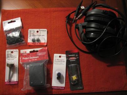
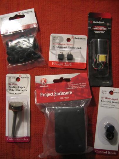
Here’s everything I got from Radio Shack. Since I’m sacrificing an existing headset, I didn’t need the jacks, plugs, and microphones from aircraft spruce or anything.
Upper left is assorted grommets – $2
Right from there, two stereo 1/8″ panel-mount jacks – $3
Lower left is a 5K Ohm audio-taper potentiometer – $3
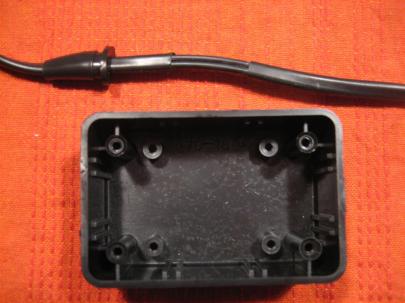
Then a 3″x2″x1″ project enclosure (perfect size) – $2.50
Then two 1/4″ knobs (for the potentiometer) – $2
Then an audio output transformer – $3
Okay, let’s get to sacrificing!
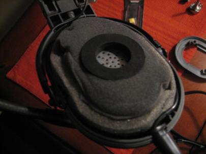
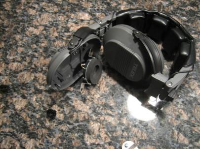
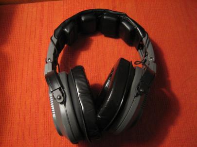
I peeled off the ear cups of my old headset, pulled back some foam, and saw a couple screws.
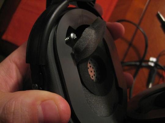
I was trying to make this non-permanent in case the project didn't work out, so I'm trying to be really careful.
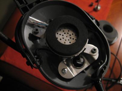
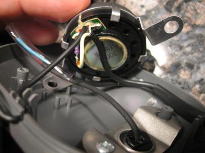
The source electrons are coming in from the cord on the right. One conductor pair connects to the micrhone wires and goes back to the bottom right, which is an exit for the mic boom. The other pair goes through a resistor on the speaker and then on to the speaker in the other ear cup.
Since I am using my nice audio headphones, I don’t need to worry about the speaker stuff.
I carefully marked the microphone wires and heated up the soldering iron to start taking stuff apart.
After getting the wires disconnected, I unscrewed the retaining plate (lower right corner of the previous picture) and took apart the little plastic ball that holds the boom in place.
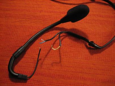
Sweet. Now I have what I need, the mic, boom, and cords that go to the proper aviation style jacks.
I had this grand plan to not even touch the mic wire. I’d just let it run straight through the project enclosure.
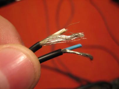
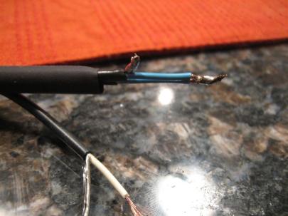
I stripped a little covering off of the wiring run and tried to figure out which wire to cut.
Then, I proceeded to find the mic wire, run my finger down to my now stripped wire run, and…
CUT THE WRONG WIRE!!!!!
Ugh.
So, I went ahead and cut both.
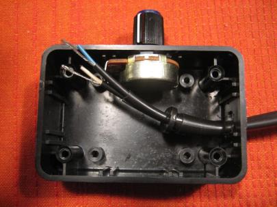
Before I get too far with wiring, I need to figure out how this potentiometer works.
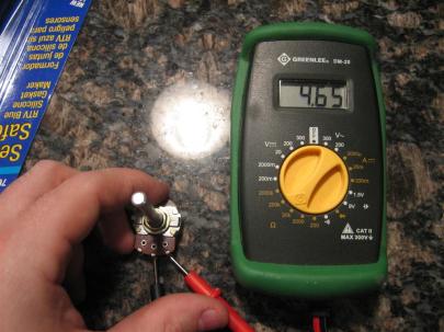
First, I hooked up my multimeter across the two outer terminals, and it read 4.65 KΩ no matter what the position of the pot.
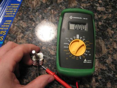
Then, I hooked up my multimeter across the left and center terminals, and it read 0.00 KΩ when turned counter clockwise and 4.65 KΩ when turned counter clockwise. (I want a lot of resistance (no signal) when it’s turned counterclockwise).
Sure enough, when I hooked it up to the right and center terminals…
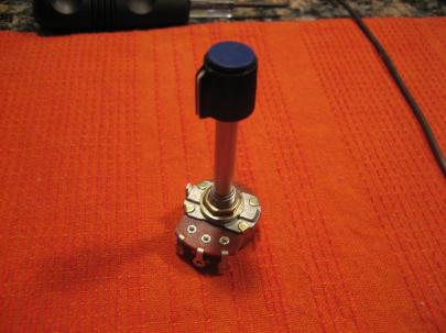
Now, let’s attach the knob.
I took it out to the garage and did a little metal removal.
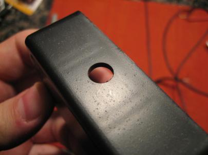
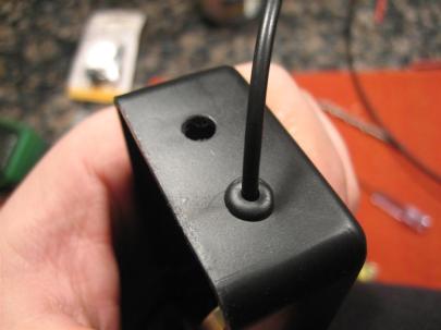
Then, back inside to drill a few carefully place holes in the project enclosure.
Okay, I’ve thought carefully how I want this laied out. I’m going to lay this thing on it’s edge to the left of my left thigh when flying.
So, the volume knob is on top, the wires going to the plane jacks can go forward (or aft, because the knob turn direction is constant no matter which way the box is rotated), and the microphone and headphone jack will be on the other side.
Clear as mud?
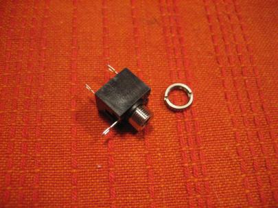
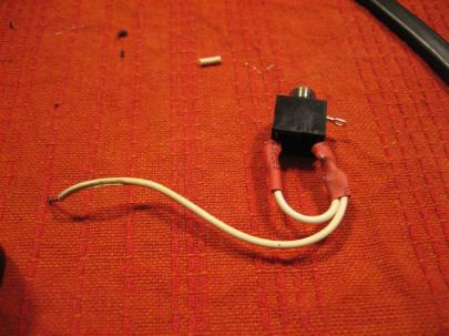
Then, I pulled out some of the other parts. Here’s my stereo 1/8″ (phone) jack that works with most headphone plugs.
Note: My original headset is mono, so instead of pulling apart the plugs to make it stereo, I’m going to make a mono version to make sure this all works out okay. If it works well, I may try again, this time in stereo (with some music inputs, perhaps?).
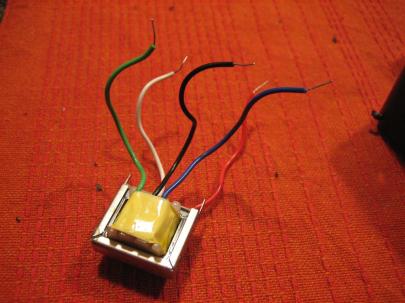
Okay, then I moved on to this really weird critter, the audio output transformer.
Without going into too much detail, there is a primary side which connects to the high impedance part of your circuit, and a secondary side, which connects to the low impedance side.
I looked at my proposed audio panel (GMA 240) and it’s output is rated at 150Ω impedance. I looked up my Klipsch headphones, and they are 18Ω impedance. I looked at my trusty David Clark headset (which seems to work great in every airplane) and it is 300Ω per speaker, or (since they are wired in parallel), 150Ω total impedance.
So I need to bump the 150Ω down to 18Ω.
“But Andrew”, you say, worriedly. “You bought a 1000Ω to 8Ω audio output transformer!!!!”
Yes, but (from my quick conversations with some of our avionics guys) the transformer is really a ratio thing.
Let’s say I just plugged my headphones into the jack. Since they are such low impedance, the audio coming from the panel would overdrive my headphones (because it’s putting enough power out for a higher impedance speaker). I’d turn the radio down so far for a correct volume that the guy (or girl) in the other seat wouldn’t be able to hear anything.
Really, it’s more important that the headphones are matched impedance, within reason of the audio output.
Anyway, if I bump down the 150Ω by a ratio of 1000/8, it would be something like 1.2Ω. That’s no good.
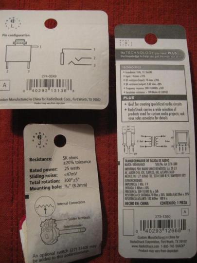
Based on the back of the transformer packaging, I tested the Primary side (the one with green, black, and blue wires) of the transformer for DC resistance. It was supposed to be 70Ω.
When I tested the Green and Blue, it was 70Ω. When I tested the black and blue, it was 35Ω. Yes! I think I read something about this! I’ll just use black and blue and theoretically, I’ll get 150*(8/500) or 2.4Ω. Not exactly 18Ω, but better than overdriving the headphones.
Okay, let’s run some more wires so I can start putting this bad boy together!
Then, I soldered the microphone wires back together just like they were in the old headset cup.
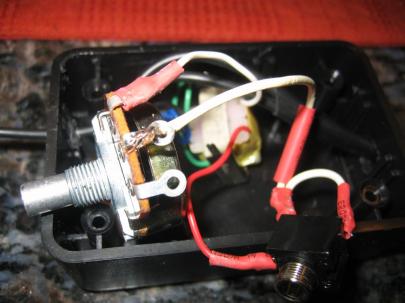
Then, I hooked up the white wire from the secondary (8Ω) side of the transformer to the poteniometer.
Then, I turned my stereo jack into a mono jack. (Remember from your wikipedia reading that tip is left, ring is right, and sleeve is ground.)
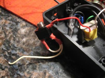
Then I hooked up the other wire of the secondary side of the transformer to the jack.
Then, the left/right side of the jack to the center connector of the potentiometer.
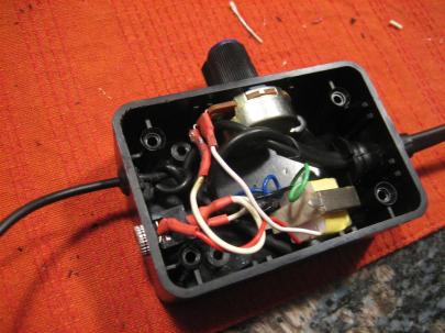
Then, very delicately mount everything and push everything into the box.
WUHOOO!
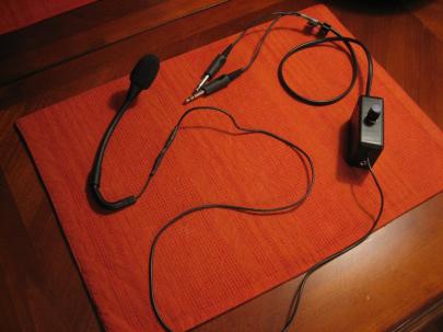
So, the existing mic from the old headset will somehow me mounted to my head (people have used heatshrink-covered piano wire, etc.), then that wire will go down, through my control box and into my audio panel through the old jacks.
My nice earbuds will plug into my control box, then go through the potentiometer (for volume) and the transformer (for impedance matching) and then to the audio panel.
As a test, I plugged my David Clarks into my home stereo system and set it to a reasonable volume. Then, I pulled in my new earbuds into my DIY headset box, then into the stereo (having turned down the volume on the box) and then slowly started raising the volume without touching the stereo system volume. When I got close to full volume, the volumes MATCHED!
WUHOOOOO!
I’m going to trust that the microphone works just like it did before, since all I did was unsolder and resolder. Now that I know the volumes match, I’m pretty sure this thing is going to work.
Tomorrow at work I’ll plug them in and see how it works.
Someone’s going to need to give me a ride in their airplane so I can compare the David Clarks with the new headset. (I’m also curious to see if my Klipsch earbuds are going to be as noise-attenuating as they are normally.
Another great night! (Doesn’t count as build time, though, since it’s not RV specific.)



Hi Andrew, thanks for your excellent instructions! I copied your build: http://www.moni.bd-4.org/blogs/122bg/?p=138
Hi – you say that you use the green & blue side of the transformer but you never explained where/what you attached them to…only the white and red which was clearly explained.
I have the same transformer and it is putting out 32 on the green/black or 64 ohms on the blue/green.
I need to go from a 150ohm system down to a 32ohm system but I don’t know exactly how to wire it up. Do i use the green/black 32 or the blue/green 64?
If possible, can you also explain where you got the 8/500 math from? I saw that the transformer is 1000ohm input / 8 ohm output but got lost when you did the calculation: “150*(8/500) or 2.4Ω.”……where did the 8/500 come from?
Thanks.
Hi Mark. You want to use the wire combination (black and green or blue and green) that yields the closest ratio to your desired 150Ohms/32Ohms. Since I bought a transformer whose ratio was 1000/8, using the blue and green would been too much (Changed the signal ideal for 150 Ohm impedence to a signal ideal for 1.2 Ohms…really cut the signal down), so I used the black wire, which is convienently half. That’s how I got the 500/8. It’s just half of the 1000/8. If I were you, I would use the black and blue (those are the ones I used. Your signal might be too soft though, since your headphones have more impedence (32 Ohm) than your signal is optimized for (you changed it from 150 Ohms down to 2.4 ohms). I have good earbuds, so the softer signal is okay, but you may want to find a different “ratio” transformer and use either the full ratio (green blue) or half ratio (black blue) wires.
Man, I hope this makes sense.
Sounds great….I’m doing it step by step to ensure all components work in the EMB145. This trip I’ll be testing some noise cancelling in-ear headphones for any noise…..if there is noise I’ll use the transformer on them.
Next up is the microphone, I plan to either use a mic stripped from a proper aviation headset or:
http://www.ebay.com/itm/Headset-Microphone-Double-earhook-1-8-3-5mm-Male-Screw-plug-Connector-NEW-/280885382969?pt=LH_DefaultDomain_0&hash=item416612cf39#ht_500wt_1413
something like that…hopefully it’ll work and then I would officially have the lightest headset on the planet.
I’ll keep you posted. Thanks for the help.
Mark
Hey there, Thanks again for the help you gave me. I got my headset working flawlessly! Active noise reduction works so well I have people wanting me to build them one too!
Which leads me to another question…if you would be so kind as to read this post I made on a forum and see if you can help me with the question posted there. It’s regarding the Microphone pre-amp:
http://www.airlinepilotforums.com/hangar-talk/68409-avionics-headset-elec-question.html#post1219166
I would appreciate it very much!
Thanks again!
Mark, how did you built the active noise reduction?
hi Andrew,
you should put this on youtube for laymen like me. this is amazing. trying to understand, but still missing somethings.
is the potentio meter absolutely necessary?
Like Mark touched on, the write up is perfect except for one thing – there’s no mention to what the blue and black wires from the transformer go to. Obviously to the incoming headphone jack from the airplane =) But which goes to which? When toning the headphone jack out, I get:
Earphone jack’s tip – Blue wire & Yellow wire.
Earphone jack’s ring and sleeve – Black wire and sleeve
So (clearly proving I am electronically challenged), does the transformer’s blue wire go to the earphone jack’s tip (blue wire and yellow wire that I’ll join together) and the transformer’s black wire go to the earphone jack’s ring and sleeve (black wire and sleeve). I’m “guessing” that’s the way it should work, but don’t wan to damage anything if it doesn’t work =) I’ve taken some pics and will post once I get it all up and working.
Again Andrew, fantastic write up – best I’ve found online, especially the parts list!!
Cheers,
Mark.
Hey Mark. I’m going to do my best to answer.
I can’t remember if someone told me or I just tried it out…but it didn’t matter which (blue or black) wire I connected. I think the audio transformer is not sensitive to polarity.
(I do think I tried to connect the blue wire and red wire (from transformer sides) to one wire that was cut, and the green and white wires (from transformers sides) to the other wire that was cut.)
Regardless, it’s a passive device, and I don’t think you’ll blow out any speakers.
Physics aside, when you test the device with a stereo or something, turn the master down (and the potentiometer down). Play some music, and increase the master volume from the stereo to make sure that the potentiometer is turned down. Put the music volume at some normal volume and start slowly increasing the potentiometer.
I’m still not sure I’m answering your question, though.
Hope this helps.
Thanks Andrew! Especially for the quick response… I thought it may be months until you saw this. If it doesn’t matter, I can try either way and see how it sounds.. That’s all I needed! Will definitely post back on my outcome.
Cheers!
Hi Andrew,
It looks like you haven’t made any posts in a few years, but I stumbled across your build log while researching how to make a knockoff halo qt headset. I appreciate the time and detail you put in to your post. How did they perform? Did you ever add an audio in port?
Side note, I started looking at your other posts as well. Did you finish your RV? I’d like to build one some day.
Thanks,
Chad