Alright, a little off-topic, but I have to talk about food for a minute. Friday night, I got home from a very hard day at the office, and my wonderful girlfriend announced we are having steak (see? I told you she was wonderful). I also nailed the cooking times on the grill.
Then on Saturday, she announced we were having “the best chili you will ever have” for our football date (see! amazing!).
Vandy lost, UNC won, but more importantly, the chili was amazing. Let me know if you want the recipe, but beware, it calls for a cup of strong coffee and a bottle of dark beer. Crazy good recipe, though.
Okay, back to the airplane.
After a big day on the house, I decided that tonight was all about the ribs.
I scoured a few build sites for ideas, but I basically need to come up with wire routing for the wings. I’m going to use tables to stay organized.
|
||||||
So I clearly need more stuff in the left wing than the right wing, but I decided to drill everything the same way.
As far as the ribs are concerned, there are two flavors of ribs with respect to the tooling holes as provided in the ribs from the factory. (They talk about flavor of ribs in the manual, too, but they are talking about part numbers and flange orientations, I am talking just about the tooling hole arrangements.)
There are 14 total ribs.
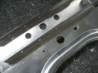
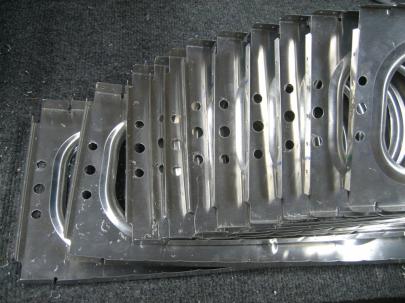
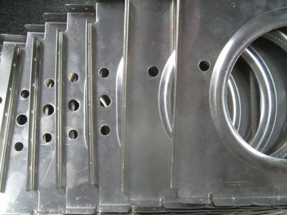
The first 11 ribs (counting from inboard to outboard) have three tooling holes in the front part of the web (just behind the main spar). The top and bottom holes are small, and the middle one is 7/16″. I decided (based on a lot of other builder’s sites, and the guidance from the Construction FAQs from Van’s that I’ll enlarge the top and bottom holes to 3/8″. (I’ll get to the other flavor of ribs in a little.)
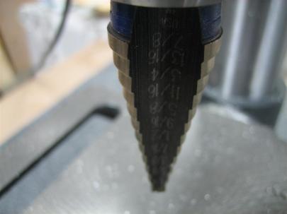
By the way, I used my brand new #4 Unibit to drill these. I stared at the Unibit from harbor freight (~$15) for awhile, and then decided this is probably something I am going to use a lot and appreciate if it is higher quality. I sprung for the $42 one from Lowes-Aviation.
So, after knocking all of the right wing ribs out, I gathered up the left wing ribs, labelled their positions and orientations, and did those 3/8″ holes, too.
The next flavor of ribs are the three outboard ribs (I’m missing one from the picture, look further down.)
They come with one hole in the forward part of the rib. I decided that I would just enlarge that hole to 3/8″ and not try to duplicate all three holes. (The construction FAQ sheet referenced earlier only talks about enlarging tooling holes in this location, not creating new holes.)
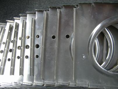
Here's the outboard most rib (upside down from the rest). Van's wants you to leave this one now for help in aileron alignment. I can deal with that.
Now, back to the construction FAQ. Van’s does let you drill a brand-spanking-new 3/4″ hole.
An additional hole may be drilled in the lower 1/3 of the rib between the large lightening hole and the next one aft. This hole may be up to 3/4” diameter to accommodate our wiring conduit (DUCT NT 5/8-50) or Bushing SB750-10 (5/8” I.D.). The conduit is light and flexible. It’s .810 “ outside diameter means that when snapped into place, the corrugations hold it from slipping out. If using the conduit, a dab of fuel tank sealant or RTV should be put on the conduit at each rib to prevent the conduit from being cut through over time from vibrations.
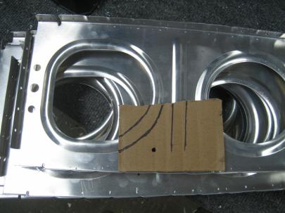
Sweet. I created a makeshift template. and started marking the center of the hole.
(Some people go crazy with this alignment. After reading a lot of other experiences, I reminded myself that this is a flexible conduit hole. They don’t have to be perfectly aligned. Although, after everything was all said and done, they were pretty darn aligned.) Don’t waste a lot of time here on a special tool. Cardboard worked great.
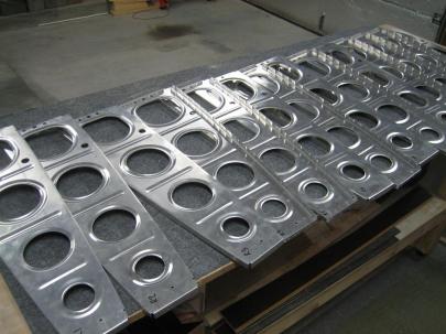
So, after punching 28 3/4″ size holes in both the left and right wing ribs, this is what I ended up with. (Really 3 flavors.)
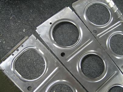
11 inboard ribs each side with 3 holes and a conduit hole, 2 outboard-ish ribs each side with 1 hole and a conduit hole, and 1 outboard rib with 1 hole (that needs to be enlarged) and a conduit hole.
Of course, I had to lay out all the right wing ribs for this completely unnecessary picture.
Okay, now that I’ve drilled the maximum amount of approved holes in each of the ribs, let’s figure out where this stuff should go.
|
|||||||||||||||||||||||||||||||||||||||||||||||||||||||||||||||||||||||||||||||||||||||||||||||||||||||||||||||||||||||||||||||||||||||||||||||||||||||||
*The plans show Pitot tube installation after the 9th rib, or in the same place as the tiedown and aileron bellcrank. It’s going to be cramped in there, so I might move the installation one bay further out. Or maybe two bays further out…I have the holes for it. (Stall warning will go one bay outboard of tiedown.)
Anyway, those are my plans for now, but I’m sure things might change. For one, I need to look more at the tiedown/pitot tube geometry. I think it will be too cluttered in the bellcrank bay, but any further outboard, and the pitot tube might be in the way of the tiedowns (low wing short airplane means tiedowns will be at a small angle.) I don’t want the tiedowns getting hung up in my expensive pitot tube.
1 hour.
